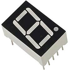
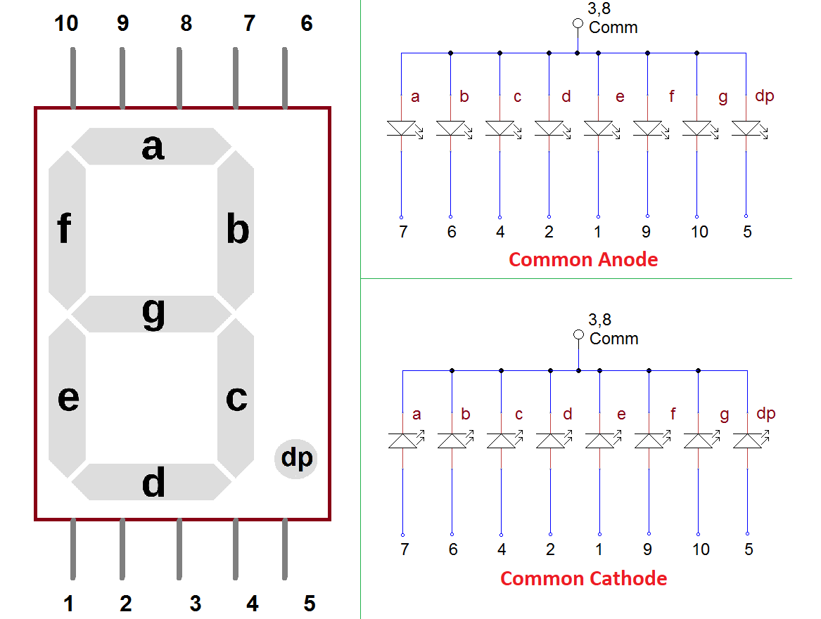
Seven segment display:
Raspberry Pi:
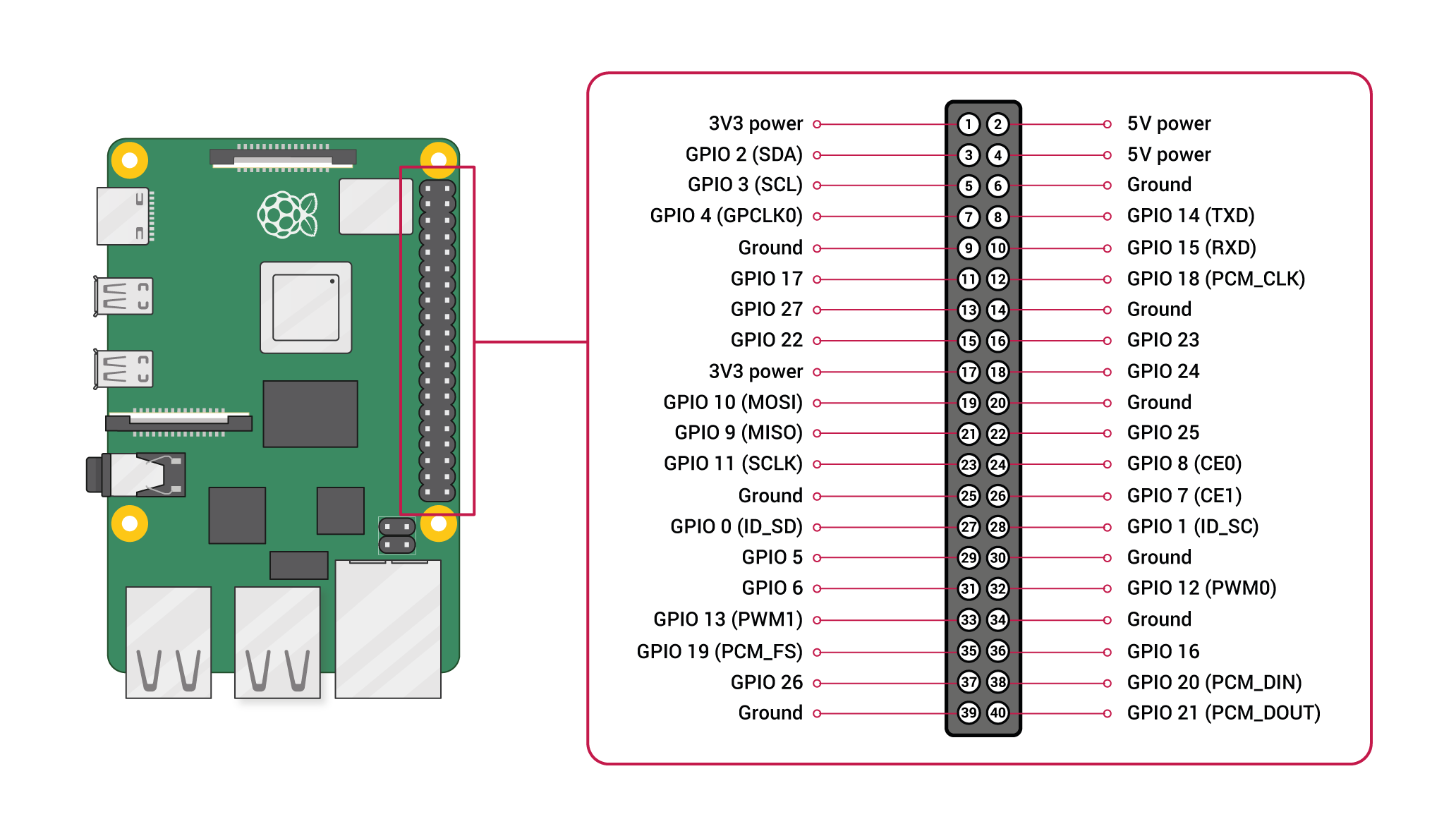
Pin configuration:
1. Vin: Two 5v pins and two 3v3 pins used for providing power supply, where processor works on 3.3v.
Seven segment pins connections with Raspberry pi:
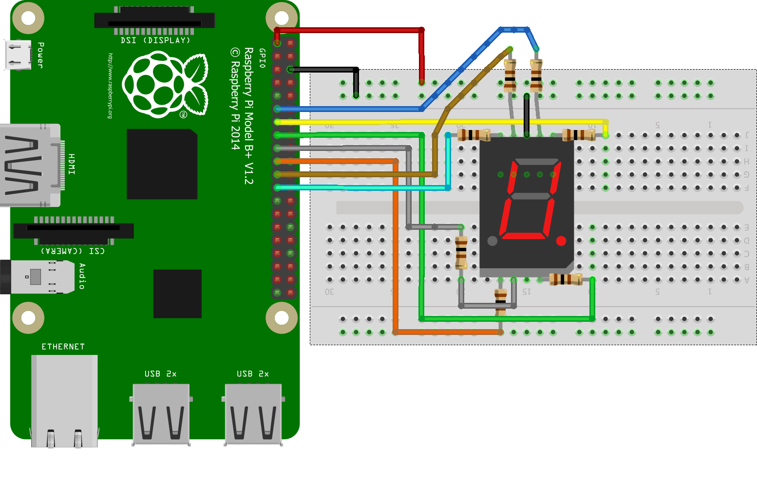
import RPi.GPIO as GPIO
import time
DISPLAY=[0x3F,0x06,0x5B,0x4F,0x66,0x6D,0x7D,0x07,0x7F,0x67]
GPIO.setwarnings(False)
GPIO.setmode(GPIO.BCM)
GPIO.setup(13,GPIO.OUT)
GPIO.setup(6,GPIO.OUT)
GPIO.setup(16,GPIO.OUT)
GPIO.setup(20,GPIO.OUT)
GPIO.setup(21,GPIO.OUT)
GPIO.setup(19,GPIO.OUT)
GPIO.setup(26,GPIO.OUT)
GPIO.setup(12,GPIO.OUT)
Def PORT(pin)
	if(pin&0x01==0x01):
		GPIO.output(13,1)
	else:
		GPIO.output(13,0)
	if(pin&0x02==0x02):
		GPIO.output(6,1)
	else:
		GPIO.output(6,0)
	if(pin&0x04==0x04):
		GPIO.output(16,1)
	else:
		GPIO.output(16,0)
	if(pin&0x08==0x08):
		GPIO.output(20,1)
	else:
		GPIO.output(20,0)
	if(pin&0x10==0x10):
		GPIO.output(21,1)
	else:
		GPIO.output(21,0)
	if(pin&0x20==0x20):
		GPIO.output(19,1)
	else:
		GPIO.output(19,0)
	if(pin&0x40==0x40):
		GPIO.output(26,1)
	else:
		GPIO.output(26,0)
	if(pin&0x80==0x80):
		GPIO.output(12,1)
	else:
		GPIO.output(12,0)
While 1:
	For x in range(10):
		Pin=DISPLAY[x]
		PORT(pin)
time.sleep(1)